
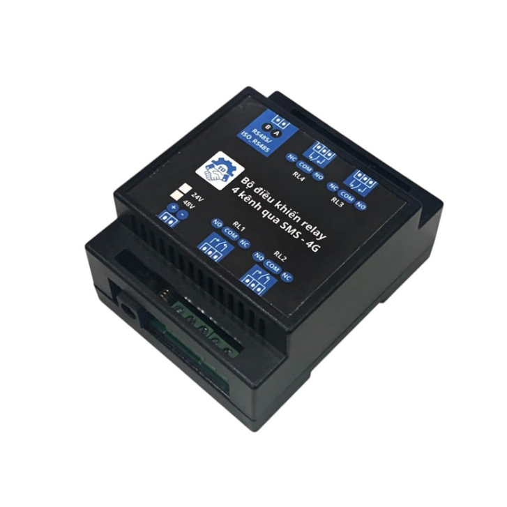
TDM2312 4-Channel Relay Module with SMS Controlled via 4G
360,000 ₫
SKU: TDM2312
Danh mục: Remote Control device
Input Voltage: 11–13V (can custom up to 48V)
Output: 4 relay channels with COM, NC, NO terminals
Relay Max Current:
- 10A at 250VAC
- 8A at 250VDC
Optional Waterproof Enclosure (not included):
- Waterproof Plastic Box 100x68x50mm with Mounting Tabs and Clear Lid
- Or: Waterproof Plastic Box 100x68x50mm with Mounting Tabs
📖 User Guide
Power Setup & Initialization:
- Supply 12V power (make sure to disconnect the programming circuit).
- Confirm the onboard LED is lit.
- Check the SIM module LED is blinking. If not:
- Measure voltage at VCC-GND pins.
- Ensure 4V is present at capacitor C7 on the board.
- Wait 10–15 seconds. If the onboard LED blinks slowly, the module is successfully connected.
- Use SMS command set to control relays.
A. Status Check
Send an SMS to the module’s phone number with the following syntax:
Command: A Response Example: Relay: 1 OFF 2 ON 3 ON 4 OFF
B. Relay Control (Registered Numbers Only)
Relay Numbers: 1 to 4 (or up to 6 depending on module type) Syntax: #Command##RelayList# Where:
Commandoptions:B: Turn ON with responseb: Turn ON without responseT: Turn OFF with responset: Turn OFF without response
RelayList: List of relay numbers to control
📲 Examples
Example 1: Turn ON relays 1, 2, and 4 with status feedback SMS: B124 Response:
Code:
Control OK!
Relay:
1 ON
2 ON
3 OFF
4 ON
Example 2: Turn OFF relay 1 without feedback SMS: t1
| Model | 24V, 48V |
|---|