English
ESP32-C3 TDM2507 Power Measurement Module Test Guide
Circuits that use 220V alternating current (AC) voltage are dangerous. Please COMPLETELY DISCONNECT THE POWER SUPPLY before proceeding with the connection operation. Re-energize only when all joints have been thoroughly checked and secure insulation is ensured.
I. Hardware Connection Instructions
1. Component List
- 01 Power Measurement Sensor Module (TDM2507)
- 01 Current Transformer (CT).
- 01 Alternating Current (AC) Power Supply Plug.
- 01 Central microcontroller circuit (ESP32C3).
- Jumpers in colors.
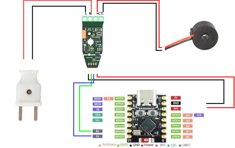
2. High voltage part connection guide
Make the connection at the wiring station assembly (green Domino) located at the top of the Power Measurement Module. Note: Screw tightening is required to avoid electric motors.
| Equipment/Conductors | Plug Position (On Module) | Function |
|---|---|---|
| AC Plug (Red Wire) | L Leg | Phase Wire (Hot) of 220V mains |
| AC Plug (Black Wire) | Pin N | Neutral (Cold) wire of 220V mains |
| CT Coil (Red Wire) | Pin + (Cluster +CT-) | Positive Current Variable Signal |
| CT Coil (Black Wire) | Leg – (Cluster +CT-) | Negative Current Variable Signal |
3. Low Voltage Part Connection (Communication with Microcontroller)
Connect at the 4 headers located at the bottom of the Power Measurement Module to transmit data and supply DC power to the system.
| Pins on Module (Left to Right) | Wire color on diagram | Connecting to the Microcontroller |
|---|---|---|
| Pin No. 1 (Far left) | Black | GND Foot (Mass) |
| Pin No. 2 | Green | RX Pins |
| Pin No. 3 | Blue | TX Foot |
| Pin No. 4 (Far right) | Red | 5V Pin (Power Supply) |
Absolutely do not pass both wires (L and N) at the same time through the CT coil because the magnetic field will cancel each other out, resulting in a measurement result that is always displayed as 0.
Detailed wiring diagram:
II. Instructions on how to load code and read sensor data
1. List of required resources
- Code test: Download at GitHub
- Feedback Reader Tool (Tera Term): Download the software here
2. Instructions for loading the code
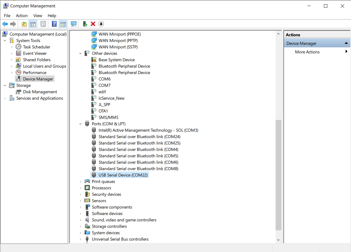
Step 1: After connecting the microcontroller (ESP32-C3) to the computer, check which COM port the device is receiving by opening Device Manager.
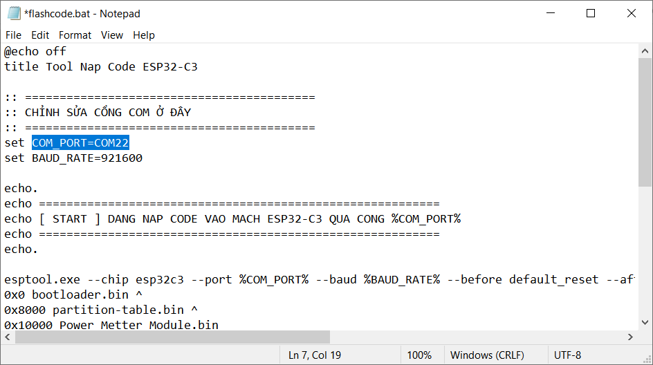
Step 2: Once you’ve identified the COM port, go to the folder that contains the code file you just downloaded. Right-click on the file and select Edit.flashcode.bat

Step 3: Proceed to fix the COM port according to the data you just saw in Device Manager. After editing, press Ctrl + S to save it.
Step 4: Finally, right-click on the file you just edited and select Open (Or double-click to run). At this point, the code will be automatically loaded into the ESP according to your port.flashcode.bat

3. Check the actual data
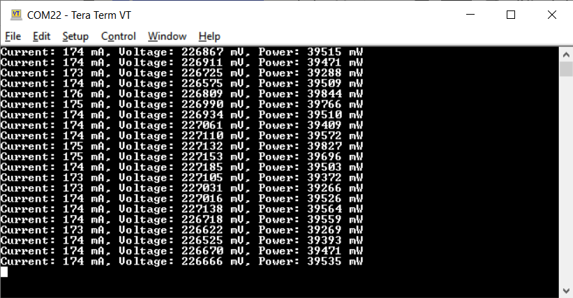
After loading the code, we proceed to read the log to check the measurement parameters:
- Open the Tera Term software.
- Check the Serial section and select the correct connection port to open the communication port with the microcontroller.
- At that time, the data on voltage, current, and power will be continuously updated and displayed on the screen.