English
LCD 2.8 Inch Datasheet
Product Parameters
| Item | Specification |
|---|---|
| Product Name | Product 1: 2.8″ TFT Display Module + Capacitive Touch |
| Product 2: 2.8″ IPS Wide-Viewing-Angle Display Module + Capacitive Touch | |
| Display Mode | Transmissive |
| Resolution | 240 × RGB × 320 pixels |
| Color Format | RGB565 |
| Display Interface | 3-wire SPI / 4-wire SPI / 8-bit MCU Parallel / 16-bit MCU Parallel |
| Viewing Direction | TFT: 12 o’clock viewing angle |
| IPS: Full viewing angle | |
| LCD Driver IC | ST7789V (Sitronix) |
| Touch Controller IC | GT911 (Goodix) |
| Maximum Touch Points | 5-point multi-touch |
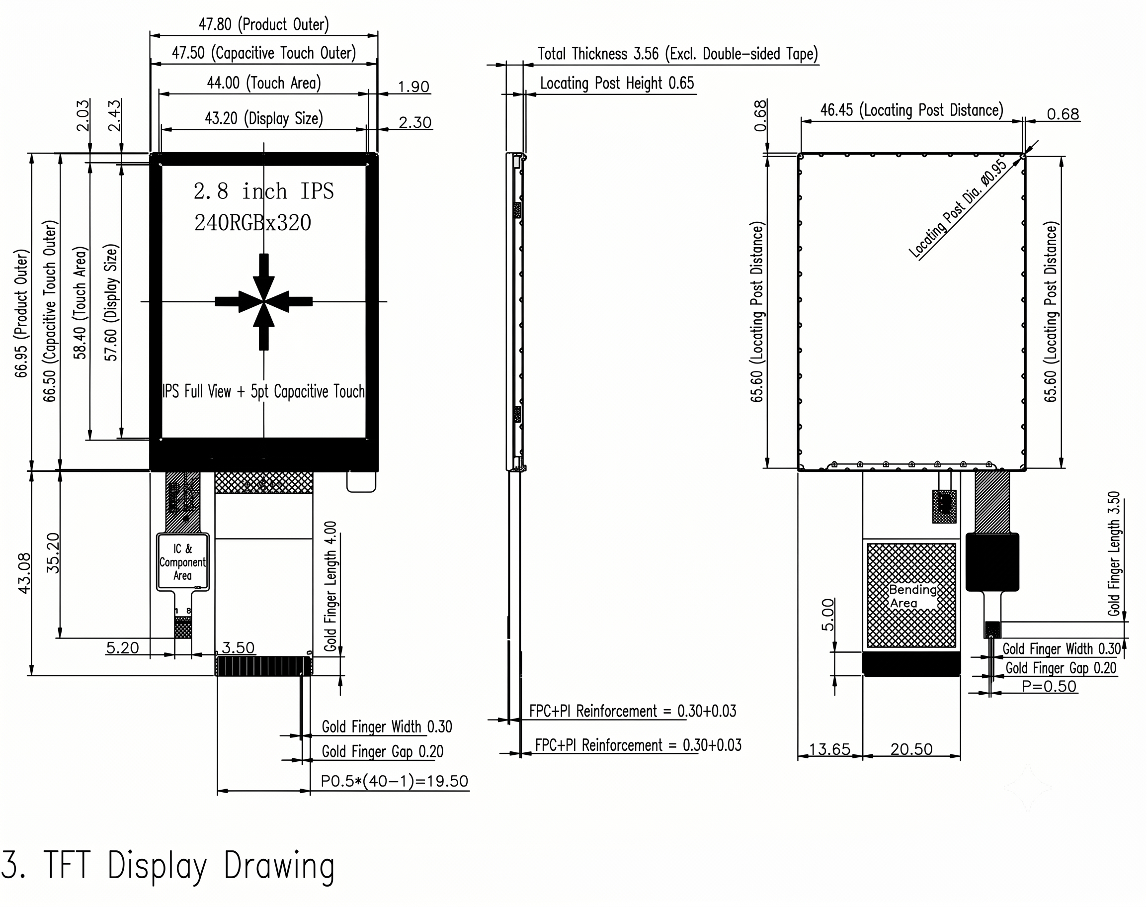
| LCD Module Dimensions | 47.80 × 66.95 × 2.13 mm |
| LCD + Touch Panel Dimensions | 47.80 × 66.95 × 3.56 mm |
LCD Drawing:
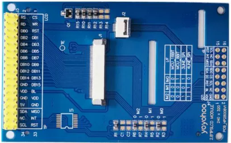
LCD Module Pin Definition (TFT & IPS Common)
| Pin No. | Pin Name | Function Description |
|---|---|---|
| 1-4 | NC | Not connected |
| 5 | GND | Ground |
| 6 | VDDI | Display I/O power supply, 1.8V to 3.3V |
| 7 | VDD | Display module power supply, 2.8V to 3.3V |
| 8 | TE | Tearing effect signal, used for synchronization; can be left unconnected if not used |
| 9 | CSX / SPI_CS | LCD controller chip select, active low |
| 10 | DCX / SPI_SCLK | Parallel mode: Command/Data select (DCX=1: data, DCX=0: command) SPI mode: Serial clock (SCLK) |
| 11 | WRX / SPI_DC | Parallel mode: Write enable signal SPI mode: Data/Command select (DC=1: data, DC=0: command) |
| 12 | RDX | Parallel read enable signal. Tie to VDDI or GND if unused |
| 13 | SPI_MOSI | SPI data input (MOSI) |
| 14 | SPI_MISO | SPI data output (MISO), leave unconnected if unused |
| 15 | RESX | Hardware reset, active low |
| 16 | GND | Ground |
| 17-32 | DB0-DB15 | Data bus lines |
| 33 | LED-A | Backlight anode supply, 3.0V to 3.3V, typical 3.1V |
| 34-36 | LED-K | Backlight cathode. Connect to GND through current-limiting resistor if brightness control is not required |
| 37 | GND | Ground |
| 38 | IM0 | Interface mode selection |
| 39 | IM1 | Interface mode selection |
| 40 | IM2 | Interface mode selection |
Touch Pinout table:
| Pin No. | Pin Name | Function Description | Remarks |
|---|---|---|---|
| 1 | GND | Ground | – |
| 2 | RST | Capacitive touch panel reset signal | – |
| 3 | INT_3.3V | Capacitive touch panel interrupt signal | – |
| 4 | SDA | Capacitive touch panel I²C SDA signal | – |
| 5 | SCL | Capacitive touch panel I²C SCL signal | – |
| 6 | VCC_3.3V | Capacitive touch panel power supply (3.3V) | – |
Reference PCB connector