
 English
I2C INSTRUCTIONS
EG800K & EG800AK Module — Part 2: I2C
This document instructs I2C communication on QuecPython (module machine. I2C), including initialization, register read/write, address scanning on the bus, and a real-world example of reading the accelerometer SC7A20HTR via I2C2 on the EG800K.
1. Overview
I2C (Inter-Integrated Circuit) is a 2-wire serial communication standard (SCL – clock, SDA – data), commonly used to connect sensors, EEPROM, RTC, etc. with modules. On QuecPython, I2C is manipulated through the machine layer. I2C, works in master mode.
Important Note: The number of I2Cn channels (I2C0/I2C1/I2C2) and the corresponding pair of SCL/SDA pins are fixed according to the hardware of each module line — not reconfigurable with code. Check the Hardware Design/pinout of the EG800K or EG800AK to see which I2C channel is being given which pin on the board you are using.
2. Layer Machine. I2C
2.1. Initialization
from machine import I2C
# I2C(I2Cn, mode)
i2c = I2C(I2C. I2C2, I2C. STANDARD_MODE)
| Parameter | Type | Meaning |
| I2Cn | int | Physical I2C channel: I2C. I2C0, I2C. I2C1, I2C. I2C2… (depending on how many channels the model supports). |
| mode | int | Bus speed: STANDARD_MODE (100kHz), FAST_MODE (400kHz), some models have ENHANCED_FAST_MODE. |
Each I2C channel should only initialize (create an object) once in the entire program. If you have multiple devices sharing a bus, simply create an I2C object and share a different slave address when calling read()/write().
2.2. Write() Method — Register Recording
i2c.write(slave_addr, reg_addr, addr_len, data, data_len)
| Parameter | Meaning |
| slave_addr | The 7-bit I2C address of the slave device. |
| reg_addr | bytearray contains the register address to be written to (e.g. bytearray([0x20]))). |
| addr_len | The number of bytes of reg_addr (usually 1). |
| data | The bytearray contains the data to be written. |
| data_len | The number of bytes of data to be written. |
2.3. Read() method — reads registers
i2c.read(slave_addr, reg_addr, addr_len, r_data, data_len, delay)
| Parameter | Meaning |
| slave_addr | The 7-bit I2C address of the slave device. |
| reg_addr | The bytearray contains the register address to be read. |
| addr_len | The number of bytes of reg_addr. |
| r_data | empty bytearray to receive the read data about (size = data_len). |
| data_len | The number of bytes to read. |
| Delay | Time-out (ms) between sending an address and reading data—some sensors need processing time before returning results. |
Note about data types: The register address (reg_addr) and data (data/r_data) parameters are required to be bytearray, not int or regular list passes — this is a very common mistake when switching from MicroPython/Arduino to QuecPython. Both read()/write() functions return the result code (0 = success), so check the return value to debug when the communication fails.
3. Address scan on the bus (I2C scan)
Before writing a driver for a new sensor, it is recommended to scan the entire I2C address range (0x03–0x77) to confirm if the device is responsive (ACK), and what the actual address is—many sensors have 2 addresses available depending on the SDO/SA0 pin logic level (GND or VDD connection).
- Scan by sending a 1-byte test read to each address in the valid range, recording addresses that return a successful code (ret == 0).
- If no device is found: double-check the sensor power supply, whether the SCL/SDA wire is connected to the correct pin on the selected I2C channel, and whether there is a pull-up resistor on the bus (some boards do not have a built-in pull-up).
- This technique is useful for knowing only which IC family compatible sensor (e.g. register compatible SC7A20HTR LIS3DH series) but not sure of the default address on the actual board.
4. Practical example: reading SC7A20HTR accelerometer (EG800K, I2C2)
The demo below illustrates the entire process above: scan the bus to determine the address, initialize the sensor via the configuration register, read the recognition register (WHO_AM_I) to confirm the communication, and then read the 3-axis acceleration data continuously.
4.1. Driver process
- I2C initialization at channel I2C2 (EG800K: pin68 = SCL, pin69 = SDA — fixed pin according to module hardware, no need for separate battery configuration).
- Read the WHO_AM_I register to confirm the sensor responds to the correct ID before further configuration—this helps detect wiring/misaddressing errors early.
- Record the CTRL_REG1 register to enable the 3 X/Y/Z axes and select the output data rate.
- Record the CTRL_REG4 register to select the scale (full-scale, e.g. ±2g) and high-resolution mode.
- Read 6 bytes of output data (X/Y/Z, 2 bytes each) by enabling the auto-increment bit at the register address, then merge the bytes and convert them to g units according to the sensitivity corresponding to the selected scale.
4.2. Test run results
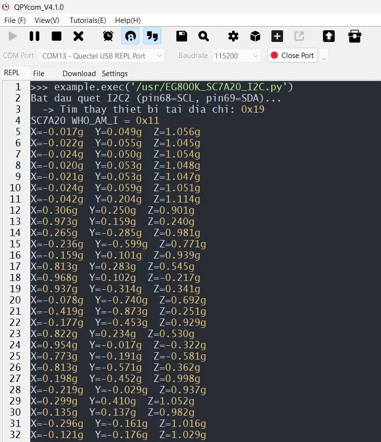
The REPL snapshot below (QPYcom) shows a bus scan that finds the device at the 0x19 address, reads WHO_AM_I=0x11 to confirm the sensor is correct, and then continuously prints the real-time 3-axis acceleration value—Z data ≈ 1g when the sensor is at rest (gravity), and change in direction when tilting/shaking the board.
Full Source Code (GitHub): https://github.com/quanminhwork2404-create/DEMO-EG800K-EG800AK/blob/main/project/EG800K_SC7A20_I2C.py
5. Practical differences between EG800K and EG800AK
- They both share an API machine. I2C — the sensor driver code written for the EG800K that can be reused on the EG800AK, as long as the correct I2Cn channel is selected with a pin on the board.
- The number of available I2C channels and the corresponding pair of SCL/SDA pins vary between the two models — the correct Hardware Design documentation for each module should be reconciled, not assuming the same EG800K when switching to EG800AK or vice versa.
- Always run i2c_scan() when switching drivers to a new board/module, even when using the correct sensor again, to reconfirm the address and channel before believing the old code.
6. Common mistakes
| Phenomenon | Common causes | How to handle |
| I2C.write()/read() returns another 0 | Wrong slave address, missing pull-up, or wrong SCL/SDA pin | Run i2c_scan() to confirm the address and if the bus is responsive |
| TypeError when calling write()/read() | Pass int or list instead of bytearray for address/data parameters | Always wrap the value with bytearray([…]) before transmitting |
| WHO_AM_I other readable datasheet | Wrong register address, not enabled auto-increment when reading multiple bytes, or misreading the sensor | Reconcile the datasheet, check the MSB bit of the register address when reading consecutively |
| Continuous false/noise reading data | Lack of delay between command and read, or sensor instability after configuration | Add sleep_ms() after the configuration register recording steps, using the delay parameter of read() if the sensor requires it |
7. References
- QuecPython API Reference — machine. I2C (developer.quectel.com/python.quectel.com)
- Hardware Design & pinout for EG800K and EG800AK (Quectel documentation) to define I2C channels and available SCL/SDA pins
- Datasheet SC7A20HTR (LIS3DH family register compatible) to look up the full configuration register table
The next part (SPI, UART, DVP Camera, etc.) will be added in the next documents.